Hydrogen is seen as a promising energy source of the future, particularly in aviation. In order to store it efficiently on board commercial aircraft, it is liquefied, i.e. kept cryogenically at -253 °C. This minimises its volume. This minimises its volume, but the cold temperatures place high demands on the materials used.
Depending on the material composition of the tank, different types can be distinguished. Types I to III contain a metallic liner and type IV a polymer liner as a sealing layer. A type V tank, on the other hand, consists exclusively of fibre-reinforced plastic (usually carbon fibres, i.e. CFRP) and does not require a liner at all. This design has several advantages: it reduces weight, avoids fatigue problems at the interface between the liner and the fibre composite and could also simplify production in the future.
However, the challenge lies in the dual function of the CFRP material: it must not only withstand the structural loads, but also ensure impermeability to the volatile hydrogen. Especially at cryogenic temperatures, the plastic matrix of the composite material can become brittle and tend to form microcracks. If these cracks form a network, there is a risk of leakage with potentially serious consequences.
Understanding the formation and propagation of such microcracks is a central component of current research work. A decisive parameter in this context is the fibre volume content (FVC). It describes the proportion of fibres in the total volume of the laminate and significantly influences the mechanical properties of the laminate. It is likely that deviations from the nominal FVG also influence the cracking behaviour at the microstructure level. Such deviations have already been observed in the manufacture of conventional pressure tanks of types I to IV in the form of gradients in the FVG across the thickness of the laminate. However, these were not considered critical in terms of tightness, as this was ensured by the liner. For the linerless type V tanks for cryogenic hydrogen storage, however, these gradients are again very relevant and are therefore the focus of this research work.
Tracking the resin flow with pipe samples and pressure sensors
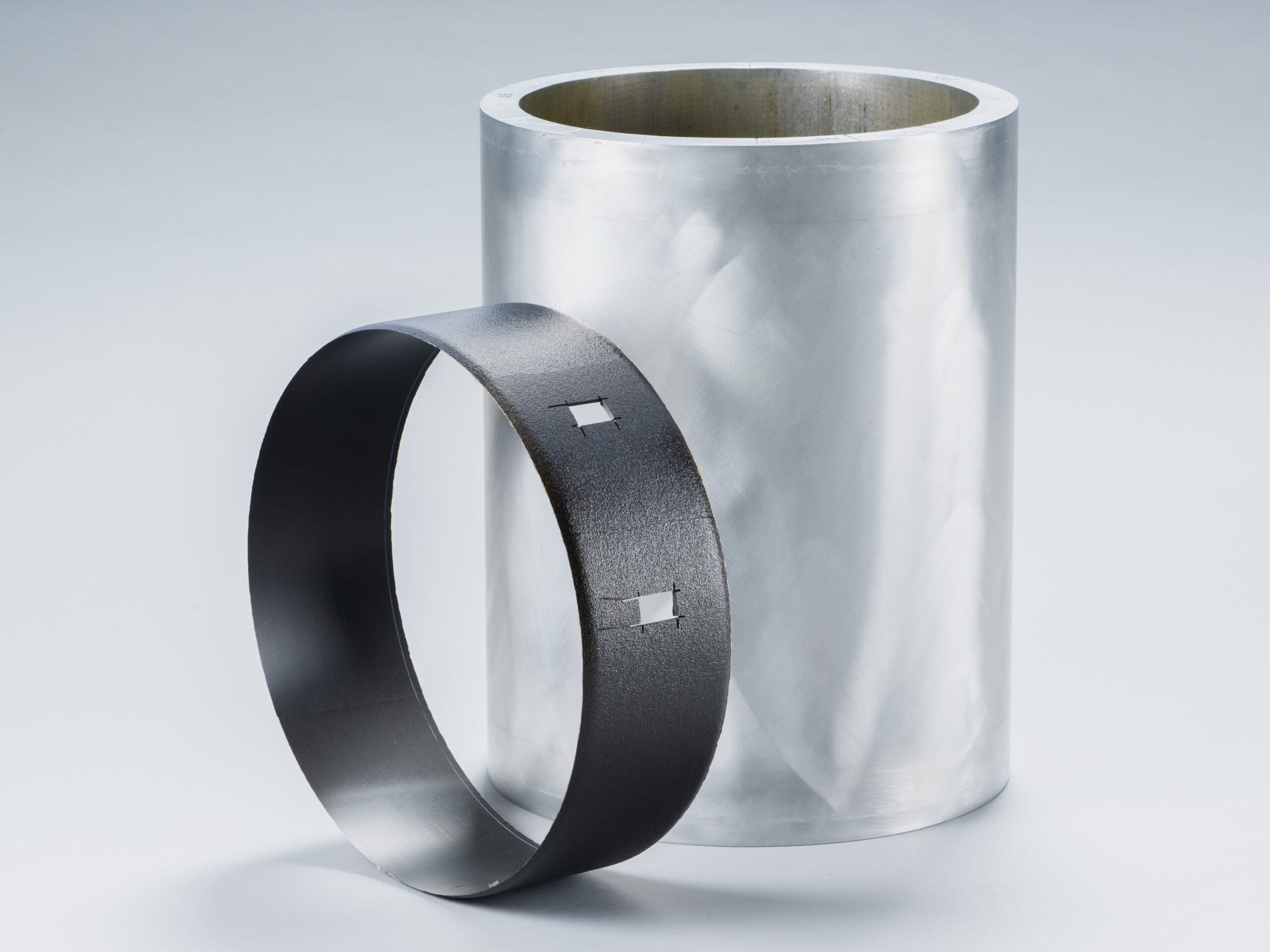
In order to get to the bottom of the causes of such gradients, a simple but effective sample design was developed: cylindrical tube samples placed on hollow metal moulds, as shown in the illustration on the right. For this purpose, duromer prepreg – i.e. carbon fibres pre-impregnated with resin – was wound onto the tool under different conditions in the circumferential direction. The prepreg material (Hexcel 6376 and Teijin Q183), the tool material (aluminium vs. steel), the autoclave cycle and the preload during lay-up were varied. Two different material types were deliberately chosen for the material selection. Hexcel 6376 is a conventional resin system without toughening modifiers, while Q183 is a fast-curing and toughening modified system.
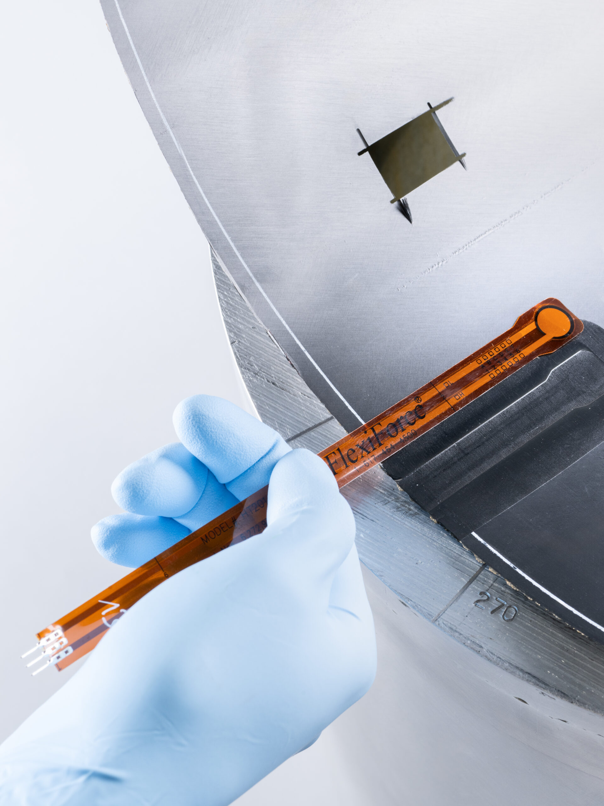
The exciting phase in researching the gradients in the FVG is the curing of the material in the autoclave. Here, the sensor shown below records the contact pressure between the mould and the laminate during the entire curing cycle. From this data, conclusions can be drawn about the fibre tension and the resin flow, which ultimately leads to the gradients. After curing, the micrographs are created and segmented using machine learning in order to generate heat maps of the local FVG.
What happens during curing? An insight into rheokinetics
The physical processes could be deciphered by taking measurements during the curing process: While the metal tool expands as the temperature rises, the carbon fibres tend to contract more in the longitudinal direction. This leads to the tool being constricted by the fibres. The resulting pressure on the contact surface was recorded by the sensor. As the temperature rises, the resin loses viscosity, becomes softer and soon even flowable. The fibres under tension move closer to the tool core in order to reduce the tensile stress and press the resin outwards. A volume exchange of resin and fibres therefore takes place. The decrease in tensile stress can be measured as a pressure drop at the inserted sensor and thus correlated precisely with the resin flow.
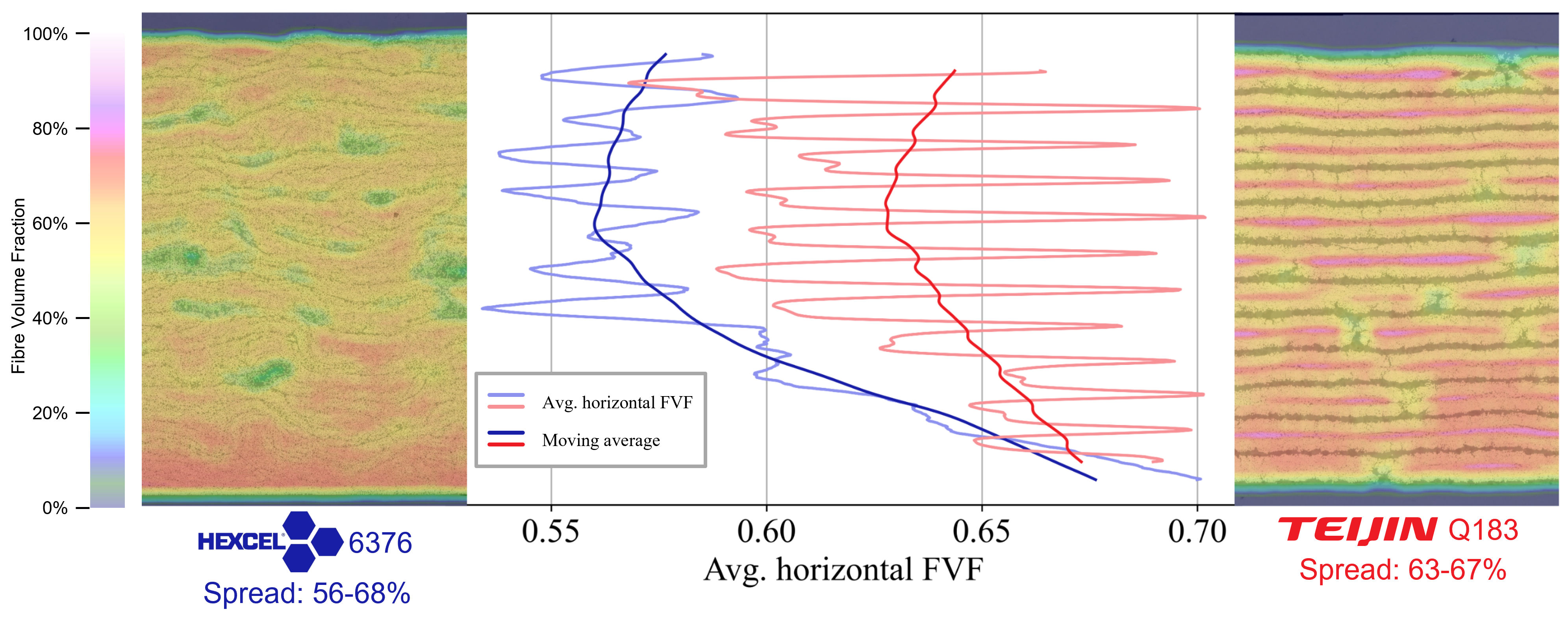
By analysing micrographs, the extent of the resin flow becomes clear. An internally developed segmentation algorithm based on machine learning visualises the local FVG in the form of a heat map. The following figure compares the two materials used with otherwise identical parameters
The lower side of the samples close to the mould systematically exhibits a higher FVG than the layers further out. The differences between maximum and minimum are up to 12 percentage points in the case of Hexcel 6376 and 4 percentage points in the case of Teijin Q183. In the world of CFRP, these are enormous deviations. When designing new materials, deviations of just one percentage point are already considered relevant. The high values are partially relativised when it is taken into account that the effect of resin flow is deliberately provoked and intensified by the specific choice of process parameters in this experimental study and that the prepreg materials used are not specifically designed for this application.
What does this mean in practice?
With these findings, clear recommendations for reducing the gradient in the FVG can be derived: Resin systems with a higher viscosity and short gelling time help to reduce the FVG gradient. The mould material also plays a role: steel with lower thermal expansion is preferable to aluminium. And a modified curing cycle with a longer holding phase at a lower temperature also shows positive effects. The preload during winding is less decisive in this study.
And what happens next?
The research results show how large the discrepancy can be between a planned design and the product of real production. The aim of future research projects is to show how these gradients in the FVG influence the microcrack behaviour. In order to realise type V tanks for cryogenic hydrogen storage in aviation, the processes from production to the end of a tank’s life must be understood in detail and controllable. This research makes an important contribution to this – for the mobility of tomorrow.